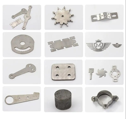
Characteristics of deep drawing deformation of rectangular parts
Deep drawing of rectangular parts is an asymmetric forming process, and its deformation characteristics differ significantly from those of rotating parts. This is primarily manifested in uneven deformation—corners and straight edges deform differently and influence each other. This unevenness makes rectangular parts more susceptible to defects such as wrinkling, cracking, and uneven wall thickness than cylindrical parts. Therefore, targeted design of process parameters and mold structure is required. A thorough understanding of the deformation characteristics of rectangular parts is key to ensuring forming quality.
The deformation zones during deep drawing of rectangular parts can be divided into corner regions and straight-side regions, each experiencing different stress and strain states. The corner regions are similar to those experienced during deep drawing of cylindrical parts, with the material primarily subjected to radial tensile stress and tangential compressive stress, resulting in plastic deformation with radial elongation and tangential contraction, and a slight increase in thickness (approximately 5%-10%). The straight-side regions, on the other hand, experience deformation similar to bending, with the material bending at the die corners. The straight-side regions, under radial tensile stress, experience a slight elongation (approximately 1%-3%), with minimal thickness change. For example, when deep drawing a square part with a side length of 100 mm and a corner radius of 20 mm, the radial elongation in the corner regions can reach 8%, while that in the straight-side regions is only 2%-3%. This difference results in uneven stress distribution at the bottom of the part, with significant stress concentration near the corners.
Deformation nonuniformity varies with the aspect ratio and fillet radius of the rectangular part. When the aspect ratio (long side/short side) of a rectangular part is close to 1 (such as a square), deformation is relatively uniform. As the aspect ratio increases, the deformation of the straight edges approaches pure bending, and the difference between the deformation and the corner deformation increases. A smaller fillet radius increases the deformation at the corners (lower drawing coefficient) and increases the susceptibility to cracking. A larger fillet radius (closer to a circle) brings the deformation closer to that of a cylindrical part, and the nonuniformity decreases. For example, when drawing a rectangular part with a 5mm fillet radius (a 2:1 aspect ratio), the maximum thinning rate at the corners can reach 15%, while the straight edges only experience 5%. When the fillet radius increases to 20mm, the difference in thinning rate between the corners and the straight edges decreases to 3%-5%. Therefore, when designing rectangular parts, the fillet radius should not be too small (generally no less than 5 times the material thickness) to reduce deformation nonuniformity.
When deep-drawing rectangular parts, the material flow exhibits a “few corners and many straight edges” pattern, resulting in uneven springback and dimensional deviations at the part’s mouth. During the drawing process, material from the straight edges tends to flow toward the corners to replenish material consumed there. However, due to the constraints of the straight edges, this flow is limited, resulting in insufficient material supply in the corners and a tendency to break. Furthermore, the reduced material flow and greater springback in the straight edges cause the mouth to expand outward. However, due to the high tensile stress in the corners, springback is minimal, resulting in relatively stable mouth dimensions. For example, after deep-drawing a low-carbon steel rectangular part, the springback in the straight edges can reach 0.5-1mm, while in the corners it is only 0.1-0.2mm. This results in an uneven mouth and necessitates additional shaping steps.
During the deep drawing process, the wall thickness of rectangular parts exhibits significant unevenness: the wall thickness in the corners initially decreases and then increases, while the wall thickness in the straight-edge areas changes less significantly. The transition between the rounded corners and the straight edges is prone to sudden changes in thickness. In the initial stages of deep drawing, tangential compressive stress in the corners causes material flow toward the center, resulting in wall thinning (a reduction of up to 10%-15%). Later in the drawing process, radial tensile stress increases, stretching the material and further thinning the wall thickness. However, the bottom corners experience a slight increase in thickness due to bending. The wall thickness variation in the straight-edge areas is primarily due to bending deformation at the die corners, with thickening on the outside and thinning on the inside, but the overall variation is relatively small (±3%). Stress concentration at the transitions can lead to localized thinning, creating a risk point for fracture. This can be mitigated by increasing the die corner radius (rconcave = 5-10t) and optimizing the blank holder force.
The die structure and process parameters for deep drawing rectangular parts must adapt to their deformation characteristics. The die’s blank holder force should be unevenly distributed, with greater force in corner areas than in straight-side areas ( 20%-30% greater) to prevent wrinkling and excessive stretching of straight edges. The die’s corner radius should be determined based on the degree of deformation. Corner die radius rconcave = (0.5-1) × part corner radius. Straight-side die radius can be appropriately reduced (rconcave = 3-5t) to reduce material flow resistance. The number of deep drawing cycles must consider both corner and straight-side deformation. The first deep drawing should ensure sufficient corner deformation, while subsequent deep drawing cycles gradually increase the straight-side height to avoid excessive corner stretching. For example, deep rectangular parts (height/short side ratio > 1.5) require three to four deep drawing cycles. The first deep drawing cycle forms the corners, while subsequent deep drawing cycles increase the straight-side height and shape the parts to ensure uniform deformation across all parts. Through targeted design, deformation defects during deep drawing of rectangular parts can be effectively controlled, ensuring part quality.