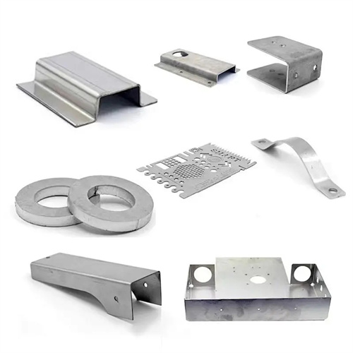
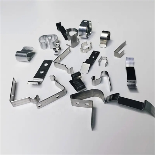
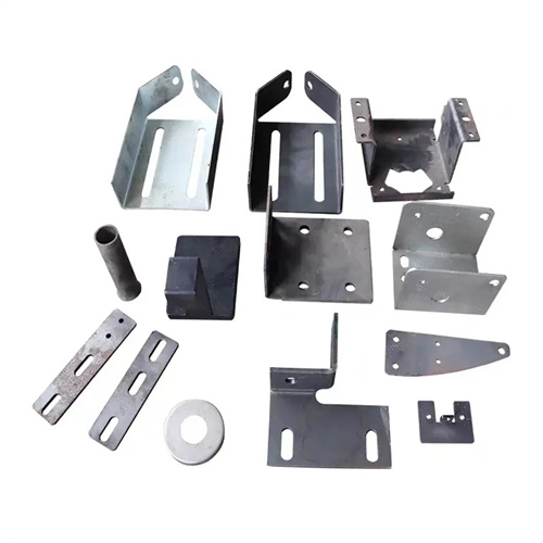
Calculation of radial dimensions of drawing convex and concave dies
Calculating the radial dimensions of the punch and die is crucial for ensuring the dimensional accuracy of drawn parts. This calculation is based on factors such as the part’s dimensional tolerance, the drawing direction (whether blanking is followed by drawing or drawing first, then punching), and whether trimming is required. The radial dimension includes the punch’s outer diameter and the die’s inner diameter; the difference between the two is the double-sided clearance. Calculations must ensure both the part’s dimensional requirements and a reasonable clearance value to ensure a smooth drawing process and a qualified part.
For parts drawn after blanking (i.e., blanking is performed first, followed by drawing), the radial dimension of the die serves as the basis for calculation. This is because the blank size after blanking is determined by the die, while the outer diameter of the drawn part is primarily influenced by the die’s inner diameter. In this case, the die’s radial dimension, D , should be the maximum limit dimension of the part to ensure that the part’s outer diameter does not exceed the maximum allowable value. The calculation formula is: D = Dmax – xΔ, where D is the maximum limit dimension of the part, Δ is the dimensional tolerance of the part, and x is the correction factor (usually 0.5-0.75, with the larger value being used for higher precision requirements). The radial dimension of the punch, d , is determined based on the die size and the clearance Z: d = D – Z. For example, if the maximum outer diameter of a drawn part is Dmax = 100mm, the tolerance Δ = 0.3mm, x = 0.75, and the clearance Z = 2mm, then Dconcave = 100 – 0.75 × 0.3 = 99.775mm, and dconvex = 99.775 – 2 = 97.775mm. This calculation method is applicable to drawing processes based on the die, ensuring that the part’s outer diameter meets design requirements.
For parts that are drawn first and then punched (such as drawn parts with a bottom hole), the radial dimension of the punch is the basis for calculation, as the part’s inner diameter is primarily determined by the punch. In this case, the punch’s radial dimension, d convex , should be the part’s minimum limit dimension to ensure the part’s inner diameter does not fall below the minimum allowable value. The calculation formula is: d convex = dmin + xΔ, where dmin is the part’s minimum limit dimension, Δ is the part’s dimensional tolerance, and x is the correction factor (same as above). The radial dimension of the die, D concave , is the punch dimension plus the gap Z: D concave = d convex + Z. For example, for a drawn part with a bottom hole, the minimum limit inner diameter, dmin, is 50 mm, the tolerance is Δ = 0.2 mm, x = 0.5, and the gap Z = 1.5 mm. Then, d convex = 50 + 0.5 × 0.2 = 50.1 mm, and D concave = 50.1 + 1.5 = 51.6 mm. This calculation method is applicable to deep-drawn parts with inner diameter as the main control indicator to ensure that the assembly dimensions meet the requirements.
For drawn parts requiring trimming, the trimming allowance must be factored into the calculation of the punch and die radial dimensions to ensure that the trimmed part dimensions remain within tolerance. For outer diameters requiring trimming, the die radial dimension must be increased by a trimming allowance, δ, calculated as: Dconcave = (Dmax – xΔ) + δ, with the punch dimension, dconcave = Dconcave – Z. For inner diameters requiring trimming, the punch radial dimension must be reduced by a trimming allowance, δ, as: dconcave = (dmin + xΔ) – δ, with the die dimension, dconcave = dconcave + Z. The trimming allowance, δ, is determined by part height and the number of draws, and is generally 1 to 5 mm (for specific values, refer to the trimming allowance selection standard). For example, the outer diameter of a drawn part that needs trimming is Dmax=80mm, Δ=0.4mm, x=0.6, δ=3mm, and Z=1.8mm, then Dconcave=(80 – 0.6×0.4) + 3=79.76 + 3=82.76mm, dconvex= 82.76 – 1.8=80.96mm. After trimming, the outer diameter can be guaranteed to be within the range of 80mm±0.2mm.
During multiple deep drawing, the radial dimensions of the punch and die must gradually approach the final dimensions for each drawing, and the diameter reduction for each drawing must be distributed according to the drawing coefficient. The die diameter for the first drawing, Dconcave₁ , = m₁ × D₀ ( D₀ is the blank diameter, m₁ is the first drawing coefficient), and the punch diameter , dconcave₁ , = Dconcave₁ – Z₁ ( Z₁ is the gap between the two sides of the first drawing). The die diameter for the second drawing, Dconcave₂ , = m₂ × dconcave₁ ( m₂ is the second drawing coefficient), and the punch diameter, dconcave₂ , = Dconcave₂ – Z₂ . This continues in this manner until the final drawing. For example, a part is deep-drawn three times, D₀=200mm , m₁=0.55 , m₂=0.7 , m₃=0.85 , Z₁= 2.4mm , Z₂=2.2mm , Z₃=2.0mm , then Dconcave₁ =0.55×200=110mm , dconvex₁ = 110 – 2.4=107.6mm ; Dconcave₂ =0.7 × 107.6 ≈ 75.32mm , dconvex₂ = 75.32 – 2.2 ≈ 73.12mm ; Dconcave₃ =0.85×73.12 ≈ 62.15mm , dconvex₃ = 62.15 – 2.0 ≈ 60.15mm , the final part diameter is close to 60mm .
The radial dimension tolerances for the punch and die are determined based on the part’s precision requirements and are typically 1-2 grades higher than the part’s tolerance. For parts with IT10 precision, the punch and die tolerances are IT8-IT9; for parts with IT8 precision, the punch and die tolerances are IT6-IT7. For example, if the part tolerance is ±0.1mm (IT10), the die tolerance can be ±0.03mm (IT8) and the punch tolerance can be ±0.02mm (IT7) to ensure that the clearance after assembly is within the designed range. The calculation of radial dimensions also needs to account for material springback. For materials with significant springback, such as high-strength steel, the die dimensions can be appropriately reduced (by 0.05-0.1mm) and the punch dimensions adjusted accordingly to compensate for the dimensional increase caused by springback. By accurately calculating the radial dimensions for each drawing pass and strictly controlling the tolerances, the dimensional accuracy of the drawn part can be guaranteed, meeting the product’s assembly and use requirements.