Mold frame, mold base, guide device
The die frame, die base, and guides are the fundamental components of the mold. Together, they provide mounting support and motion guidance for the mold’s working parts, ensuring precise fit and stable operation during the stamping process. The die frame is the mold’s skeleton, comprising the upper and lower die frames; the die base is the core load-bearing component of the die frame, securing the punch, die, and other working parts; and the guides ensure the relative motion accuracy of the upper and lower dies. The three components work together to directly impact the mold’s service life and the quality of the stamped parts.
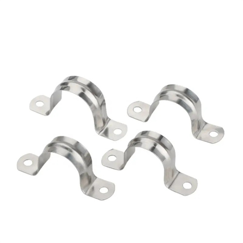
The mold frame serves as the basic framework of the mold, mainly consisting of an upper mold base, a lower mold base, guide pins, and guide sleeves. Its structure is divided into standard mold frames and non-standard mold frames according to the mold type and production requirements. Standard mold frames are manufactured according to national standards and have strong versatility and good interchangeability. They are suitable for small and medium-sized stamping molds. Common models include diagonal guide pin mold frames, rear guide pin mold frames, and intermediate guide pin mold frames. For example, the guide pins of the diagonal guide pin mold frame are installed at the diagonal position of the mold frame, which has good guiding stability and is suitable for stamping parts with higher precision requirements; the guide pins of the rear guide pin mold frame are located at the rear side of the mold, which is convenient for operation and feeding, and is suitable for large sheet metal stamping. Non-standard mold frames are customized according to the special needs of complex molds. They have flexible structures, but they have high manufacturing costs and long cycles.
The die base, consisting of an upper die base and a lower die base, is a key component that directly supports the working part and transmits force. Its material selection and machining precision significantly impact die performance. The upper die base is mounted on the press slide and moves up and down with it; the lower die base is fixed to the press table and bears the full load during the stamping process. Die bases are typically made of HT300 gray cast iron (suitable for small and medium-load dies) or Q235 steel (suitable for high-load dies). For high-precision dies, 45 steel (hardness 220-250HB) can be quenched and tempered to improve strength and wear resistance. The die base requires a flatness of ≤0.05mm/100mm and a parallelism of ≤0.1mm/300mm between the upper and lower surfaces to ensure even force distribution and prevent deformation of the working part after installation.
The guiding mechanism is crucial for ensuring mold motion accuracy. It primarily consists of guide pins, guide bushings, and guide plates. Their function is to prevent the upper and lower dies from shifting during movement and ensure uniform clearance between the punch and die. Guide pins and bushings utilize a clearance fit, typically with an accuracy of H7/h6 and a guide clearance of ≤0.01mm. For high-precision molds, precision-grade rolling guide pins and bushings are required, achieving a clearance of less than 0.005mm. The guide pins must be longer than the mold’s closed height to ensure that, when the mold is fully opened, 10-15mm of the guide pin remains within the guide bushing to prevent it from falling out. Guide plates are suitable for large molds and slide along wear-resistant plates on the upper and lower die bases. The wear-resistant plates are made of hardened T8 steel (hardness 50-55 HRC) with a surface roughness of Ra ≤0.8μm, ensuring smooth sliding.
The layout of the guide system depends on the size and shape of the mold. Small molds typically use two guide pins (symmetrically arranged), medium-sized molds use four guide pins (arranged at the four corners), and large molds require intermediate guide pins in addition to the four corner guide pins to prevent deformation of the mold base. The diameter of the guide pins is selected based on the mold size, typically ranging from 20-60mm, and the length is 3-5 times the diameter to ensure guiding stability. The guide pins and guide sleeves are installed with an interference fit (H7/r6) to ensure they do not loosen under stamping vibration. After installation, the perpendicularity between the guide pins and the die base plane should be checked to ≤0.01mm/100mm. For high-speed stamping dies, the guide system requires lubrication. Oil grooves can be provided on the guide sleeves for regular lubrication to reduce friction and wear.
The quality of the die base, die holder, and guides directly impacts the lifespan of the die and the precision of stamped parts. Excessive guide clearance can lead to misalignment between the punch and die, resulting in burrs or part deformation, and in severe cases, mold damage. Inadequate die base strength can cause deformation during the stamping process, reducing guide accuracy. For example, a stamping die experienced excessive burrs on the part after stamping due to a 0.03mm clearance between the guide pin and guide sleeve. This reduced the die lifespan from 100,000 cycles to 50,000. Replacing the guide pins and sleeves with a 0.005mm clearance eliminated the burrs and extended the die lifespan to 150,000 cycles. Therefore, during mold design and manufacturing, the precision and quality of the die base, die holder, and guides must be strictly controlled to ensure stable mold operation.