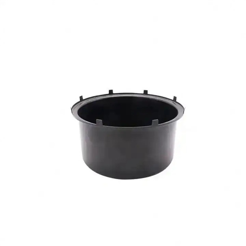
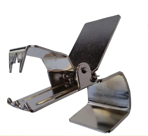
Mold structure design
Mold structure design is the premise and foundation of mold manufacturing. It transforms a product’s three-dimensional model into a machinable and assembleable mold component combination scheme, encompassing the mold’s overall structure, component layout, kinematic relationships, and strength verification. Excellent mold structure design must balance forming performance, manufacturing difficulty, and production costs, ensuring the mold meets product precision requirements while maintaining sufficient service life and production efficiency. Mold structure design typically consists of two phases: overall design and detailed design. The overall design determines the mold type and overall layout, while the detailed design refines the structure and dimensions of each component.
The overall mold structure design requires selecting the appropriate mold type based on the product’s characteristics. For example, stamping molds can be categorized as single-step, compound, and progressive. Plastic molds can be categorized as injection, compression, and extrusion. Single-step molds have a simple structure and are suitable for small-batch production of simple parts. Compound molds can complete multiple steps in a single stroke and are suitable for medium-volume production. Progressive molds are ideal for the continuous production of large-scale, complex parts. For example, a progressive die is required for stamping mobile phone casings. This involves 10-15 stations, completing blanking, drawing, punching, and bending processes, with a production rate of up to 300 times per minute. The overall design also requires determining the mold’s closing height, installation dimensions, and feeding method to ensure compatibility with the parameters of the press or injection molding machine. For example, the mold’s closing height must be within the press’s maximum and minimum closing heights, with a tolerance of no more than ±5mm.
The layout of mold components must ensure uniform force distribution and coordinated movement. The arrangement of working parts (punch, die, and core) should conform to material flow patterns to avoid localized stress concentration. For symmetrically shaped products, the parts must be arranged symmetrically. For example, in a stamping die for circular parts, the centers of the punch and die must coincide with the mold center, with a coaxiality error of ≤0.01mm. For asymmetrical products, balancing blocks or other symmetrically arranged parts must be used to offset eccentric forces and prevent vibration during mold operation. The layout of guide components (guide pins and guide sleeves) must ensure accurate guidance. Small and medium-sized molds use four guide pins (arranged at the four corners), while large molds require additional intermediate guide pins. The spacing between guide pins should be greater than the maximum workpiece size to ensure uninterrupted feeding and removal.
The design of the mold’s exhaust and cooling systems is crucial for ensuring product quality, especially for plastic and die-cast molds. The exhaust system expels air and volatiles from the cavity, preventing defects such as bubbles and material shortages. Vents are typically located on the parting surface or the side of the core, with a depth of 0.02-0.05mm and a width of 5-10mm. Large molds require multiple vents, with a total exhaust area of ≥0.5% of the cavity volume. The cooling system uses circulating water to remove heat from the forming process, maintaining a reasonable mold temperature (typically 50-80°C for plastic molds). Cooling channels should be close to the cavity surface (15-20mm away), have a diameter of 8-12mm, and a temperature differential of no more than 5°C between the inlet and outlet. For example, the cooling channels of beverage bottle molds employ a spiral layout to ensure uniform cooling across the entire bottle body, with a cooling time of 10-15 seconds.
The detailed design of the mold structure requires two-dimensional and three-dimensional drawings of the parts, noting key dimensions, tolerances, and technical requirements. The dimensions of the working parts must be calculated and determined based on the product dimensions and the forming process. For example, the clearance between the punch and die of a stamping die and the core and cavity dimensions of a plastic mold must include shrinkage compensation (usually 0.5%-2% for plastic parts). The tolerance grade of the parts must be determined based on the fit requirements, such as H7/h6 for the guide pin and guide sleeve, and H7/m6 for the punch and retaining plate. Technical requirements must specify the material, heat treatment method, and surface roughness. For example, the die material should be Cr12MoV, with a quenching hardness of 58-62 HRC and a surface roughness of Ra0.4μm. Furthermore, the detailed design must consider the part’s processability, such as using standard parts whenever possible and avoiding complex internal cavities to reduce manufacturing difficulty.
After the mold structure design is completed, it must be verified, including strength, stiffness, and motion interference checks. Strength checks ensure that mold components do not undergo plastic deformation under maximum load. For example, the die edge strength must meet σ ≤ [σ] ([σ] is the allowable stress of the material). Stiffness checks ensure that the elastic deformation of the components is within the allowable range, such as the deflection of a large mold base ≤ 0.05mm. Motion interference checks use 3D simulation software (such as UG and SolidWorks) to check for collisions between components during mold opening and closing. For example, the minimum spacing between the ejector mechanism and the core must be ≥ 1mm. Through comprehensive verification and optimization, the reliability of the mold design can be significantly improved, reducing the modification workload during mold trials.