Bending process and mold design and manufacturing
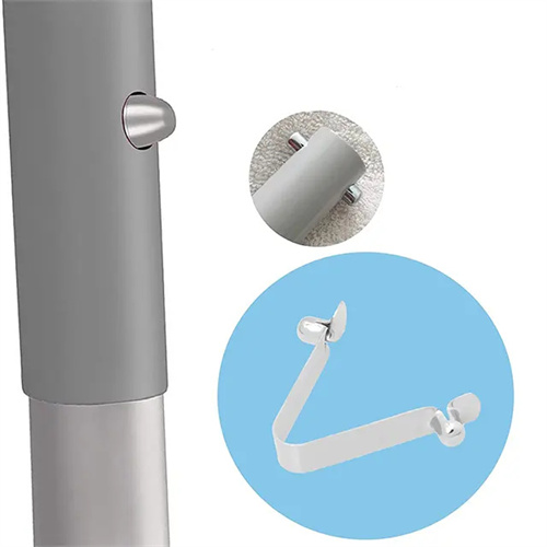
Bending is a stamping process that uses dies to bend flat blanks or profiles into parts with specific curvatures and angles. It is widely used in industries such as automotive manufacturing, electronics, and instrumentation. Parts such as automobile frames, mobile phone cases, and brackets all require bending. The core of the bending process is to induce plastic deformation in the material through external force while simultaneously controlling defects such as springback, cracking, and wrinkling to ensure the dimensional accuracy and shape requirements of the bent part. Bending processes can be categorized by the bending method, including press bending, roll bending, and stretch bending. Press bending is the most widely used in mold manufacturing due to its simplicity and efficiency.
The basic principle of bending is that when a material is subjected to a bending moment, the outer fibers stretch due to tension, the inner fibers contract due to compression, and a layer of fibers in the middle (the neutral layer) remains constant in length. The degree of material deformation during bending can be expressed by the relative bending radius (r/t, where r is the bending radius and t is the material thickness). The smaller the relative bending radius, the greater the deformation and the greater the likelihood of cracking. To avoid cracking, the minimum relative bending radius must be controlled. This varies for different materials. For example, the minimum r/t for mild steel is 0.25-0.5, for brass 0.3-0.8, and for aluminum alloy 0.5-1.0. For example, when bending a 2mm thick mild steel plate, the minimum bending radius is 0.5mm. If the designed bending radius is 0.3mm, the outer fibers will crack, requiring annealing to reduce the material’s hardness before bending.
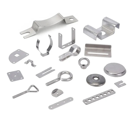
The design of a bending die requires determining the die structure based on the shape, size, and precision requirements of the part being bent. Common types of bending dies include single-step, compound, and progressive. Single-step dies have a simple structure and are suitable for simple-shaped parts (such as V- and U-shaped parts), forming them in a single pass. Compound dies can complete multiple bending steps in a single pass and are suitable for parts of medium complexity. Progressive dies are suitable for the continuous production of large-scale, complex-shaped parts, using multiple stations to gradually complete the bending process. Die design requires determining parameters such as the punch and die radius, clearance, and die depth. The punch radius is typically equal to the inside radius of the part being bent, while the die radius is (3-6)t to ensure smooth material flow into the die. For example, the die depth of a U-shaped bending die must be greater than two-thirds of the part’s height to prevent deformation during the return stroke.
The manufacturing of bending dies requires guaranteed dimensional and shape accuracy for both the punch and die. Material selection is determined by the part material and production batch. For ordinary low-carbon steel parts, the working parts can be made of hardened T8 or T10 steel (hardness 58-62 HRC). For harder materials like stainless steel and high-strength steel, Cr12MoV or SKD11 steel (hardness 60-64 HRC) should be used, with surface nitriding (hardness HV800 or higher) to improve wear resistance. The typical die manufacturing process is: forging → annealing → rough milling → heat treatment and quenching → finishing by grinding → assembly and commissioning. For example, the manufacturing process for a Cr12MoV steel punch is: forging blank → spheroidizing annealing (reducing hardness to 200-250 HB) → rough CNC milling → quenching (oil quenching at 980°C) + tempering (200°C) → surface grinding and cylindrical grinding → polishing (Ra 0.8μm).
Adjusting the bending die is crucial for ensuring the quality of bent parts. This involves adjusting the gap between the punch and die, the positioning mechanism, and the ejector mechanism. Excessive clearance can increase springback, while too small can cause surface scratches or dimensional deviations. An appropriate clearance is typically (1-1.1)t (material thickness). The positioning mechanism must ensure that the blank does not shift during bending, with a positioning accuracy of ≤±0.1mm. For asymmetrical parts, an anti-roll device is required to prevent workpiece shifting during bending. The ejector mechanism must provide sufficient ejector force to ensure smooth demolding during the return stroke while minimizing springback. During adjustment, test bends are performed to check the bend angle, dimensions, and surface quality. If the angle is out of tolerance, correction can be made by adjusting the punch stroke or grinding the die angle. If cracking is present, the bend radius should be increased or the material softened. For example, during a test bend, a V-shaped part was found to have an angle 2° greater than designed. Increasing the punch stroke by 1mm brought the required angle within the specified range.
Bending processes and mold design and manufacturing require comprehensive consideration of factors such as material properties, part shape, and production batch size. By rationally selecting process parameters and mold structure, bending defects can be controlled to ensure product quality. With the widespread use of new materials such as high-strength steel and aluminum alloys, bending processes face even greater challenges. Advanced technologies such as warm bending and hydroforming are required, along with CAE simulation software (such as Dynaform and AutoForm) to predict stress and strain distribution during the bending process, optimize mold design, reduce mold trials, and improve production efficiency.