Dimension design of the working part of the bending die
The dimensional design of the working portion of a bending die directly impacts the precision of the bent part, the life of the die, and the stability of the forming process. These parameters primarily include the punch corner radius, the die corner radius, the die opening width, and the gap between the punch and die. These parameters must be determined based on the part’s material, thickness, bend radius, and precision requirements. By combining theoretical calculations with empirical data, we ensure that the die’s working portion matches the workpiece’s forming requirements.
The punch radius (r ) is a key parameter of the working portion of the bending die and is typically equal to the inner radius (r) of the part being bent, meaning r = r. When the inner radius r is small (r < 0.5t), the punch radius can be increased to prevent cracking in the workpiece. After bending, the radius can be adjusted to the designed value in subsequent steps. For example, a part requires a 1mm inner radius and a material thickness of 3mm (r/t = 0.33 < 0.5). The punch radius is designed to be 2mm, and after bending, the inner radius is adjusted to 1mm in the shaping step. A punch radius that is too small can cause scratches or cracks on the workpiece surface, while a punch radius that is too large can increase springback and affect the accuracy of the bending angle. Therefore, it is important to select an appropriate punch radius while ensuring workpiece quality.
The die corner radius (r concave) guides material flow into the die and reduces friction during bending. Its value is typically 3-6 times the material thickness, i.e., r concave = (3-6) t. For thick materials (t > 3mm) or high-strength materials, a larger die corner radius (5-6t) is recommended to prevent edge scratches. For thin materials (t < 1mm) or materials with good plasticity, a smaller value (3-4t) can be used. For example, for a 2mm thick mild steel part, the die corner radius is designed to be 6mm (3×2); for a 5mm thick high-strength steel part, the die corner radius is designed to be 25mm (5×5). Too small a die corner radius can hinder material flow, increase bending force, and cause scratches on the workpiece. Too large a die corner radius can cause inaccurate workpiece positioning and affect bending accuracy.
The die opening width (L concave) is a critical parameter for V-bending dies. It refers to the distance between the two working surfaces of the die. Its size must ensure smooth material insertion and bending. It is typically 0.8-1.2 times the unfolded length of the part being bent, or calculated using the formula: L concave = 2r concave + 2t + (5-10) mm. For V-shaped parts, the die opening width must also satisfy L concave ≥ (12-15) t to ensure a stable bending process. For example, for a V-shaped part with a material thickness of 3mm, the die opening width L concave = 2 × 15 (r concave = 5t = 15) + 2 × 3 + 8 = 30 + 6 + 8 = 44mm. Since 15t = 45mm, L concave = 45mm. A die opening width that is too small will restrict material flow and increase bending force; a die opening that is too large will result in unstable bending angles and increased springback. Therefore, the die opening width should be appropriately selected based on the material thickness and bend angle.
The punch-die gap (Z) is a key parameter in U-bending dies. This refers to the space between the punch and die sidewalls, and its size directly impacts the dimensional accuracy and springback of the bent part. The single-side gap is typically 1-1.1 times the material thickness, meaning Z/2 = (1-1.1) t. For high-precision parts, the smaller value (1t) is used; for low-precision parts, the larger value (1.1t) is used. For example, for a 2mm thick U-shaped part, the single-side gap is 2mm for high-precision and 2.2mm for standard precision. The punch-die gap must be uniform, with an error of ≤0.05mm. Otherwise, the workpiece walls will exhibit perpendicularity deviations or inconsistent bend angles. Excessive gaps can result in significant springback, while too small a gap increases bending forces, exacerbating die wear and potentially causing surface indentations.
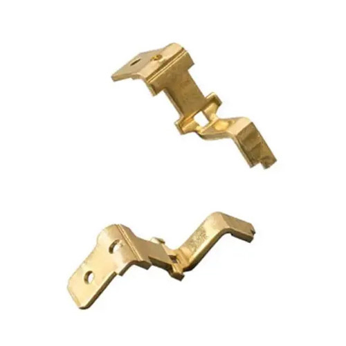
The dimensional tolerance and surface roughness of the working part of the bending die must be strictly controlled. The working surface roughness Ra of both the punch and die should be ≤0.8μm to reduce friction and workpiece scratches. Dimensional tolerances are typically IT7-IT8 to ensure matching with the workpiece’s dimensional accuracy. For example, if the dimensional tolerance of a bent part is IT10, the dimensional tolerance of the die’s working part should be IT7 to ensure sufficient precision. For areas subject to rapid wear (such as die corners), localized hardening treatments (such as carburizing and quenching to a hardness of 58-62 HRC) can be used to extend die life. Furthermore, the shape of the die’s working part must conform to the workpiece’s shape. For irregularly shaped bent parts, a contoured design is required to ensure uniform material deformation. For example, the punch and die of a wavy bent part must precisely replicate the workpiece’s wave curve to ensure consistent bending radius across all parts.
The dimensional design of the working portion of a bending die requires verification and refinement through trial molds. Parameters such as the corner radius and clearance between the punch and die are adjusted based on the dimensional accuracy and surface quality of the workpiece after the trial bend. For example, if the bend angle is too small during the trial bend, the punch radius can be appropriately reduced. If significant indentations are evident on either side of the workpiece, the clearance between the punch and die can be increased or the surface roughness reduced. By continuously optimizing parameters, the working portion dimensions of the die are perfectly matched to the forming requirements of the bent part, ultimately achieving high-quality and efficient bending production.