Bending die bending method
Bending with a die is a key process for achieving plastic deformation of materials to obtain desired part shapes. Various bending methods are used, depending on the part’s shape complexity, precision requirements, and production batch size. Each method has its own unique die structure and process characteristics. Choosing the right bending method can significantly improve production efficiency and product quality. Common bending methods include V-bending, U-bending, Z-bending, hemming, and complex multi-station bending. These methods cover the forming needs of parts ranging from simple to complex.
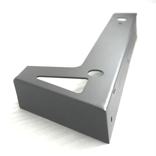
V-bending is the most basic bending method, suitable for bending flat blanks into parts with a single bend angle, such as V- and L-shapes. The mold structure is simple, consisting primarily of a punch, a die, and a positioning device. During bending, the punch presses downward on the blank, gradually bending the material into shape under the support of the die. The bending angle can be controlled by adjusting the punch stroke. The key to V-bending is to ensure that the die opening width matches the material thickness, typically 12-15 times the material thickness, to ensure a stable bending process. For example, to V-bend a 2mm thick mild steel plate, the die opening width is 25mm, the bending angle is 90°, and the blank position is controlled by locating pins. The bending can be completed in a single stroke, making it suitable for small and medium-sized batch production of parts such as brackets and connectors.
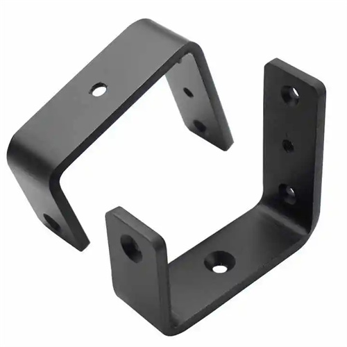
U-shaped bending is suitable for forming U-shaped, trough-shaped parts with two symmetrical bending angles. The mold structure includes a punch, a die, a pressure plate, and a push-piece device. During bending, the pressure plate first presses the blank to prevent slippage. The punch then descends, bending the material along the side walls of the die . The push-piece device supports the bottom of the blank during the bending process to prevent it from sinking. U-shaped bending requires strict control of the verticality and symmetry of the side walls. The side walls of the die are usually designed with a slope of 0.5°-2° to reduce springback. For example, a U-shaped trough part (material thickness 3mm, inner width 50mm) uses a U-shaped bending die with a 1° slope on the die side walls and a push-piece force of 10% of the bending force. After bending, the verticality error of the side walls is ≤0.1mm/100mm, meeting assembly requirements.
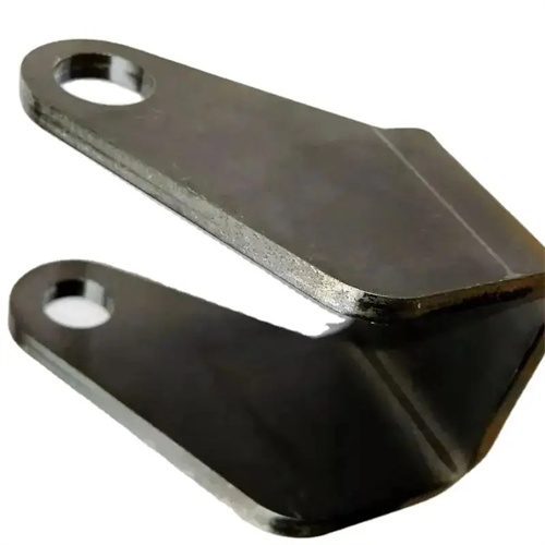
Z-bending is used to form Z-shaped parts with two opposing bend angles. The mold structure requires two punches or dies at different heights, completing the bend in one or two passes. The single-pass Z-bending die uses a stepped punch, initially bending to an acute angle and then to an obtuse angle as the punch descends. This is suitable for simple Z-shaped parts. Complex Z-shaped parts require a double bend process: pre-bending one angle before bending the other to avoid excessive stretching. For example, a Z-shaped part (30mm high and 20mm low) was formed using a double bend process: the first bend was 60°, and the second was 120°. The final shape was achieved with a dimensional error within ±0.1mm.
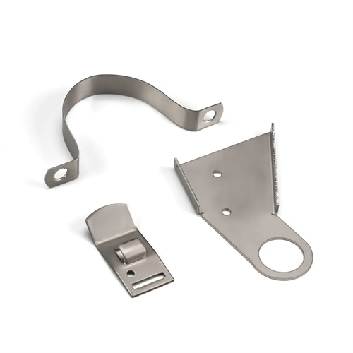
Hemming (also known as arc bending) is suitable for bending the edges of parts, such as cylindrical or semicircular parts, into an arc or curled shape. The mold structure requires a curved punch and die, and the material is gradually bent into a continuous arc. The key to hemming is controlling the consistency of the bend radius. Typically, multiple bending passes are used, each bending at a specific angle to achieve the desired arc. For example, a circular part with a diameter of 50mm uses three hemming passes: the first bend is 60°, the second is 120°, and the third is 180°. This ensures a smooth, wrinkle-free arc with a radius error of ≤0.2mm.
Complex-shape multi-station bending is suitable for complex parts with multiple bend angles and irregular contours, such as automotive panels and electronic instrument brackets. Progressive or compound dies are typically used to gradually complete the bending process through multiple stations. Progressive die multi-station bending breaks down complex bending into pre-bending, shaping, and correction steps, with each station completing a portion of the deformation. Automatic feeding mechanisms enable continuous production. For example, a certain automotive door hinge part has five bend angles. The progressive die has six stations (feeding, pre-bending 1, pre-bending 2, shaping 1, shaping 2, and cutting), achieving a production rate of 30 parts per minute and dimensional accuracy reaching IT10 level. Compound die multi-station bending, on the other hand, completes multiple bending operations in a single stroke, making it suitable for medium-volume production, reducing positioning errors and improving dimensional consistency.
When selecting a bending die method, consider the part shape, precision requirements, material properties, and production batch size. Simple parts are preferably bent using single-step processes such as V- and U-shaped bends; complex parts utilize multi-station bending. For small-batch production, general-purpose bending dies can be used, while large-scale production utilizes specialized progressive or compound dies. Furthermore, attention should be paid to the material’s bending properties. For difficult-to-bend materials like high-strength steel, warm bending or additional correction steps can be used to ensure forming quality. With technological advancements, bending methods are becoming increasingly intelligent, using computer simulation to optimize bending paths, reduce the number of die trials, and improve process stability.