Inlay die design
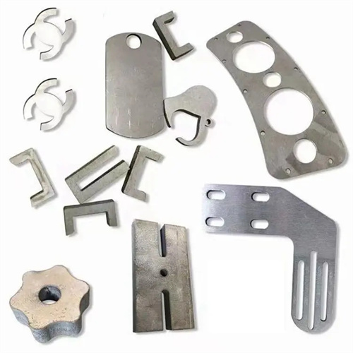
The inlay die design is a die technology that divides the key parts of the die, such as the punch and die, into several small pieces (inserts), and then splices them together. It is suitable for punching parts with complex shapes and large sizes (such as automobile covers and large electrical appliance housings). It can reduce the processing difficulty of large mold parts and reduce material waste. During maintenance, only the worn inserts need to be replaced, which can reduce maintenance costs by 30%-50%. The core is to reasonably divide the inserts to ensure that the mold accuracy after splicing meets the requirements, the matching clearance between the inserts is less than 0.01mm, and the overall flatness error is less than 0.05mm/m. In the early stage of design, the inserts need to be divided according to the shape characteristics of the punching parts, usually along the symmetry line, the turning point of the contour or the straight line segment. For example, a rectangular part can be divided into 2-4 inserts along the long side.
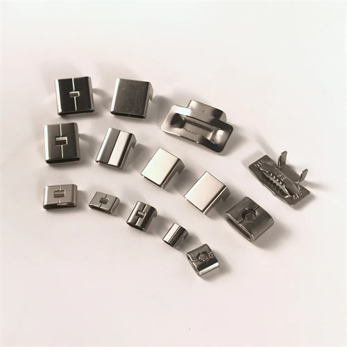
The mold structure consists of inserts, insert fixing plates, mold frames and positioning devices. The inserts are made of Cr12MoV or SKD11 alloy tool steel, with a quenching hardness of HRC58-62, the working surface polished to less than Ra0.4μm, and the cutting edge is precision ground to ensure the quality of blanking. The inserts can be fixed by bolts, blocks and dovetail grooves. Bolt fixing is suitable for large inserts (size > 200mm). The inserts are fastened to the fixing plate by hexagon socket bolts with a positioning accuracy of ±0.01mm. Dovetail groove fixing is suitable for small and medium-sized inserts. It is used with positioning pins, which is easy to load and unload, and has a positioning accuracy of ±0.005mm. The insert fixing plate is made of HT300 cast iron or Q235 steel plate, with a thickness of 1.5-2 times the thickness of the insert to ensure sufficient rigidity.
The division and splicing accuracy of inserts are key to the design. When dividing inserts, it is necessary to avoid setting splicing seams at key parts of the punching contour (such as sharp corners and narrow grooves) to prevent burrs or cutting edge cracks during punching. The direction of the splicing seam should be perpendicular to the direction of the punching force or at a certain angle to reduce the impact of the punching force on the splicing seam. The positioning between inserts uses a combination of locating pins and locating slots. The fitting clearance between the locating pins and pin holes is 0.005-0.01mm, and the fitting clearance of the locating slots is 0.01-0.02mm to ensure that the inserts do not move when subjected to force. For large molds, adjustment gaskets (thickness 0.01-0.1mm) need to be set between the inserts to compensate for processing and assembly errors and ensure the overall accuracy after splicing.
With significant application scenarios and process advantages, the inlay die is particularly well-suited for the production of large-volume, complex-shaped blanking parts. For example, the die for an automobile door panel consists of dozens of inlays, which can be individually machined and then assembled, significantly reducing the processing difficulty. For high-variety, small-batch production, replacing different inlays allows for rapid changeovers, shortening die preparation time. During blanking, the inlays must be evenly distributed. Reinforcing ribs are incorporated into the fixed plate to enhance the overall rigidity of the die and prevent deformation due to uneven force.
During commissioning and maintenance, focus on overall precision control. During mold trials, inspect the quality of the blanking at the insert joints. If burrs are present, grind the cutting edges at the joints. If the blanked part dimensions are out of tolerance, adjust the insert position by adjusting the shims. After every 5,000 parts, inspect the insert’s securement. Tighten bolts if loose, and replace locating pins if wear exceeds 0.01mm. During long-term storage, remove the insert from the mounting plate, store it separately, and apply anti-rust oil to prevent deformation from prolonged stress. Insert repair methods such as surfacing and grinding can extend its service life and reduce mold costs.