Design of Extrusion Die for Flangeless Forming Parts
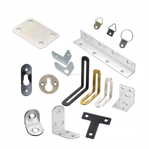
The extrusion die design for flangeless formed parts is a specialized die technology for edge trimming of flangeless cylindrical and box-shaped parts (such as bearing sleeves and small containers). Through a combined extrusion and shearing action, it removes burrs after deep drawing, resulting in a smooth finish (flatness <0.05mm) and a perpendicularity error <0.1mm/m). Suitable for materials with thicknesses of 1-5mm, such as mild steel and stainless steel, it replaces traditional turning or grinding processes, increasing efficiency by more than fivefold. Its core principle is to utilize the plasticity of the material. The extrusion cutting edge first squeezes the material at the mouth, causing it to plastically deform , and then shears away any excess burrs. The resulting surface roughness can reach Ra 1.6μm, eliminating the need for subsequent machining. The extrusion cutting edge diameter is determined based on the part diameter during design, and should be 0.05-0.1mm larger than the nominal diameter (allowing for springback).
The die structure consists of an extrusion punch, extrusion die, pressure plate, ejector, and guide mechanism. The extrusion punch is constructed of W18Cr4V high-speed steel, hardened to HRC62-65. Its cutting edge is divided into an extrusion section (with a taper angle of 3°-5°) and a shear section (with a sharp cutting edge). The extrusion section is 2-3 times the material thickness (6-9mm for 3mm thick material) to ensure sufficient plastic deformation. The extrusion die is constructed of cemented carbide (WC-Co 92%) with a hardness of HRA90-92. The clearance between the punch and the die is 3%-5% of the material thickness (0.03-0.05mm for 1mm thick material). It is secured to the die base via shrink-fitting with an interference fit of 0.01-0.02mm. The pressing plate is made of 45 steel with quenching and tempering treatment (HRC28-32). The inner hole is 0.1-0.2mm larger than the outer diameter of the part. The nitrogen spring provides a pressing force of 20-50kN to prevent the part from deformation.
The extrusion force and stroke control must be precise. The total extrusion force is calculated according to the formula F=πD t (σb + σs)/2 (D is the diameter of the part, t is the thickness, σb is the tensile strength, and σs is the yield strength). For example, for a φ50mm, 3mm thick 20 steel part, the extrusion force is about 80-100kN, of which the extrusion force accounts for 60%-70% and the shear force accounts for 30%-40%. The stroke control is achieved through the limit block. The extrusion section stroke is equal to the material thickness (3mm thick, take 3mm), the shear section stroke is 0.5-1mm, and the total stroke error is ±0.01mm to ensure thorough extrusion and cutting. It adopts hydraulic drive, with a pressure control accuracy of ±1%, a speed of 5-10mm/s in the extrusion stage, and a speed of 10-20mm/s in the shear stage to avoid impact loads.
The positioning and guiding system ensures the precision of extrusion cutting. The parts are positioned by the inner hole, and the positioning mandrel is used (the clearance with the inner hole of the part is 0.01-0.03mm). The mandrel material is Cr12MoV (HRC58-62), and the top is rounded (R1-2mm) to facilitate the loading of parts. The guiding mechanism adopts ball guide pins and guide sleeves. The diameter of the guide pin is 25-40mm, and the clearance is 0.001-0.003mm, ensuring that the coaxiality error of the extrusion punch and the die is less than 0.005mm. For parts with a height of more than 50mm, a support ring needs to be set in the middle of the mandrel to prevent the part from bending (deflection less than 0.1mm).
The material and process adaptability need to match. The extrusion die is suitable for materials with good plasticity (elongation ≥ 25%). For brittle materials such as high carbon steel, annealing treatment (600-650℃, 2 hours) is required to reduce the hardness to below HB180. Before extrusion cutting, it is necessary to ensure that the burr height of the part mouth is ≤1mm. Excessive burrs will cause overload damage to the extrusion cutting edge. For parts with uneven mouths after deep drawing, a pre-shaping station needs to be added to make the burr height difference <0.3mm. After extrusion cutting, the parts need to be stress relieved (low temperature tempering 150-200℃, 1 hour) to eliminate the residual stress generated by extrusion cutting (stress value <100MPa).

During commissioning and maintenance, attention is paid to protecting the cutting edge. During die trials, the die mouth dimensions are measured on five parts. If flatness is out of tolerance, the pressing force is adjusted (±1kN). If perpendicularity is out of tolerance, the coaxiality between the mandrel and the die is corrected. After every 2,000 parts, the cutting edge is inspected for wear (re-grinding is required if a step >0.02mm is present in the extrusion section). The guide mechanism is lubricated with high-speed grease (NLGI Grade 2) weekly to ensure smooth movement. During long-term storage, the cutting edge should be coated with anti-rust oil and the punch should be supported with a dedicated bracket to prevent deformation due to stress.