Design of non-guided universal die
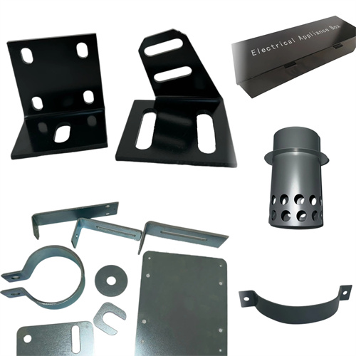
The guideless universal die design features a simplified structure, suitable for simple blanking parts such as gaskets and small brackets, with low precision requirements (dimensional tolerances IT12-IT14) and small production runs (annual production of less than 1,000 pieces). The material used is typically 0.5-5mm thick, made of mild steel or non-ferrous metals. Its key feature is the omission of the traditional guide pin and bushing guide mechanism, achieving rough positioning through the cooperation between the die and the press. This design offers a simple structure and low manufacturing cost (30%-50% lower than guided dies), but with a larger blanking clearance fluctuation (±0.1mm), making it suitable for the rapid production of repair and test parts. The die base size is determined based on the size of the press slide. The upper and lower die bases are constructed of HT200 cast iron, with a thickness 1-1.2 times that of the die to ensure sufficient rigidity.
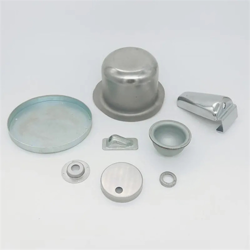
The die structure consists of an upper die (including the punch, punch mounting plate, and upper die base) and a lower die (including the die, die mounting plate, and lower die base), without any dedicated guides. The punch is made of T8A tool steel, hardened to HRC 55-58, with a 15-20° bevel on the cutting edge for easy entry into the material. The die is made of Cr12 steel, hardened to HRC 58-60, with a cutting edge clearance set at 10%-15% of the material thickness (0.1-0.15mm for 1mm thick material). Trial punching is used to adjust the clearance to ensure the absence of visible burrs. The punch and mounting plate utilize a transition fit (H7/m6), while the die and lower die base are directly bolted together. Positioning accuracy relies on manual assembly (positioning error <0.5mm). The unloading mechanism utilizes rubber or springs, with a discharge force of 5%-10% of the blanking force, ensuring smooth removal of scrap from the punch.
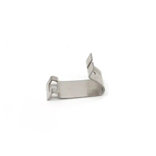
The applicable scenarios and process restrictions need to be clear. The non-guided general-purpose die is only suitable for punching parts with simple contours (such as circles and rectangles). Parts with complex shapes are prone to damage to the cutting edge due to uneven gaps. The punching force should not be too large (≤50kN). The press should be an open single-point press. The slider stroke accuracy should be <0.2mm to avoid aggravating the gap fluctuation due to the tilt of the slider. The blank needs to be manually centered during operation, and the marking positioning or the stop pin is used for rough positioning (positioning error ±1mm). The overlap of the male and female dies needs to be checked before each stamping to prevent the die from breaking due to eccentric loading. For materials with a thickness of >3mm, the punching speed needs to be reduced (<10 times/minute) to reduce the impact load.
The cost and maintenance advantages are significant, the mold manufacturing cycle is short (1-3 days), and welded structures can be used to replace some machined parts. For example, the punch fixing plate is welded with Q235 steel plates and does not require heat treatment. Daily maintenance is simple. The blade can be directly sharpened after wear without adjusting the guide gap. No special bracket is required for storage. It can be placed horizontally, but anti-rust oil needs to be applied to the blade. Since there is no guide protection, a protective net must be equipped during operation to prevent waste from splashing and injuring people. It is prohibited to feed the material directly by hand during the blanking process, and auxiliary tools (such as tweezers and push rods) must be used.
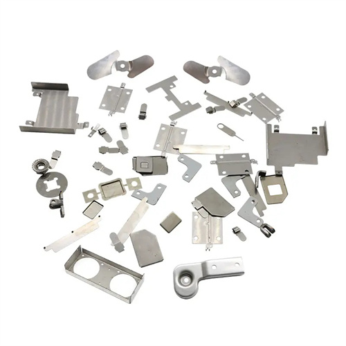
Improvements and optimizations can improve practicality. Positioning grooves (width 10-15mm) are opened on the contact surface of the upper and lower die seats, and simple guidance is achieved with positioning blocks to control the gap fluctuation within ±0.05mm. For parts with slightly larger batches (annual production of 1000-5000 pieces), 4 positioning pin sleeves can be added around the die to cooperate with the positioning pins at the corresponding positions of the upper die to form a semi-guided structure, which increases the cost by about 20%, but extends the service life to twice the original. During the mold trial, the gap needs to be adjusted in multiple batches, the best relative position of the male and female dies is recorded, and the gasket is fine-tuned to ensure stable blanking quality.