Design of automatic bending die
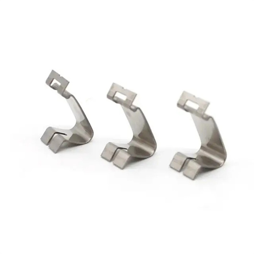
The bending automatic die design is an automated bending device that integrates mechanical transmission, pneumatic/hydraulic control and sensor detection. It is suitable for small bending parts (such as electronic component pins, hardware connectors) produced in batches. It can realize the full process automation of automatic feeding, positioning, bending and unloading. The production efficiency is 150-300 pieces per minute, and the bending angle accuracy is ±0.5°. It is suitable for materials such as copper strips and steel strips with a thickness of 0.1-2mm. Compared with manual bending dies, it coordinates the actions of various mechanisms through the PLC control system, and the response time is less than 0.1 seconds, which greatly reduces manual intervention and labor intensity. It is suitable for large-scale production in the fields of automotive electronics and consumer electronics.
The mold structure consists of an automatic feeding mechanism, a precision positioning device, a multi-station bending mechanism, an automatic unloading device, and a detection system. The automatic feeding mechanism uses a servo motor-driven ball screw with a feeding accuracy of ±0.01mm. The feeding speed can be set via the touch screen (50-200mm/s). The pneumatic gripper ensures continuous material transportation. The gripper pressure is 0.3-0.5MPa and automatically adjusts according to material thickness to prevent pinching and slipping. The multi-station bending mechanism utilizes a rotary worktable with 4-6 bending stations, each equipped with an independent bending punch and die. The punch is made of Cr12MoV (HRC58-62), and the die uses carbide inserts that can be quickly replaced to accommodate different bending angles (30°-135°).
The automatic control system is the core of the bending automatic mold. It uses PLC (Programmable Logic Controller) as the main controller and cooperates with the touch screen to realize parameter setting (bending angle, feeding length, production quantity) and status monitoring (such as fault alarm, production statistics). The sensor system includes optical fiber sensors (to detect the presence of materials), angle encoders (to monitor the bending angle in real time) and pressure sensors (to detect bending force). When an abnormality is detected (such as missing materials, angle deviation), the system automatically stops and issues an alarm. The response time is less than 0.5 seconds to avoid batch waste.
Closed-loop control of bending force and stroke ensures stable forming quality. The bending force (0.5-10kN) is provided by the servo hydraulic system, the force value control accuracy is ±2%, and the bending stroke is fed back by the grating ruler in real time (resolution 0.001mm), realizing force-displacement double closed-loop control. For materials with large rebound (such as spring steel), the system can preset the bending angle ( 1°-3° larger than the target angle), and rebound to the target angle after bending. The bending compensation value can be automatically optimized through the trial mold data to ensure that the angle deviation is less than 0.5°.
Human-machine interaction and safety protection systems improve operational convenience and safety. The touch screen interface displays real-time production data (output, qualified rate, fault information), supports parameter saving and calling (can store 100 sets of process parameters), and facilitates multi-variety switching. Safety protection uses two-hand start buttons, safety light curtains (response time <10ms) and emergency stop buttons. When a person enters the dangerous area, the equipment stops immediately, and the braking distance is <1mm, which complies with the GB 23821-2009 safety standard.
Debugging and maintenance must ensure the stable operation of the automation system. During the first debugging, the optimal process parameters (bending force, speed, and bending angle) are determined by trial bending 50 pieces and stored in the system database. Check the sensor calibration status before starting the machine every day. The detection accuracy of the optical fiber sensor must be less than 0.01mm; perform precision calibration on the servo motor and ball screw every month, and compensate when the positioning error is greater than 0.02mm. Replace the hydraulic oil of the hydraulic system every six months (contamination level NAS 8), and clean the filter of the pneumatic system once a week to ensure stable air pressure (0.6±0.02MPa).