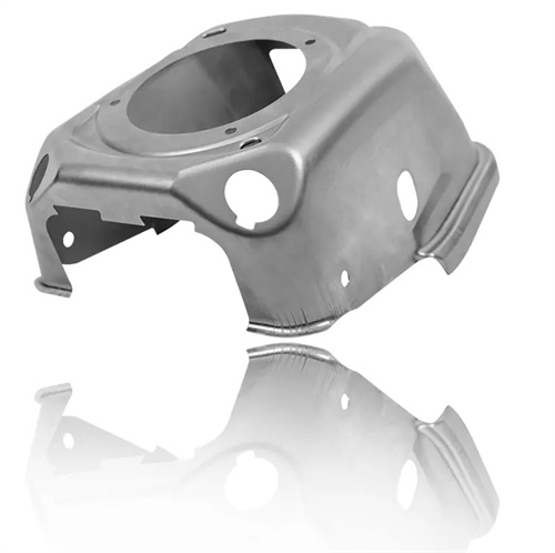
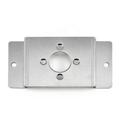
Design of the Forming Die for the Fuel Tank Plate
The fuel tank panel forming die design utilizes a comprehensive forming technology for deep drawing, flanging, and shaping thin sheet metal (0.8-2mm thick galvanized steel or aluminum alloy) used in automotive and hydraulic tanks. Complex curved surfaces (such as curved bottoms and sloped sidewalls) and sealing edges (5-15mm height) must be formed in one step, with a flatness tolerance of <0.3mm/m and a flanging verticality of ±0.1mm to ensure subsequent weld tightness (leakage <0.1L/h at 0.3MPa). The core design approach is to coordinate material flow rates to avoid necking (reduction <15%) or wrinkling during deep drawing. CAE simulations (such as AutoForm software) are used to optimize the blank holder force distribution, and a stepped blank holder (with a 5%-10% pressure increase) is implemented in the rounded corners.
The die structure consists of a drawing die, a composite punch, a zoned blank holder, a shaping insert, and an ejector mechanism. The drawing die is constructed of Cr12MoV steel (HRC 56-58), with an inner surface polished to Ra 0.1μm. The bottom corner radius is 8-12mm (the upper limit is used for aluminum alloys), and the sidewalls have a draft angle of 0.5°-1°. The composite punch is a monolithic structure (material: W6Mo5Cr4V2, HRC 60-62). Titanium plating (thickness 0.005mm) reduces the coefficient of friction to 0.08. The gap between the punch and die is 1.1-1.2 times the material thickness (1.1-1.2mm for a 1mm thickness). The zoned blank holder is divided into three to five independently controlled zones, using nitrogen springs to provide a blank holding force of 20-50kN. The pressure in each zone can be individually adjusted (accuracy: ±1kN) to meet the material requirements of different locations.
The forming process parameters need to match the material properties. The drawing speed is controlled at 50-100mm/s. The aluminum alloy takes the low speed end (50-70mm/s) to prevent cracking, and the galvanized steel plate can be increased to 80-100mm/s. The lubricant is silicon-free stamping oil (viscosity 15-30cSt), and a uniform oil film (thickness 3-5μm) is formed on the surface of the blank. After drawing, degreasing and cleaning (temperature 50-60℃, time 3-5 minutes) are used to remove oil stains to ensure welding quality. For tank plates with a depth of more than 100mm, two deep drawing operations are required: the first drawing to 70%-80% of the depth, annealing treatment (galvanized steel 180-220℃/1h) to eliminate stress, and the second drawing to the final size to reduce springback.
Sealing edge forming and quality control are key processes. The flanging adopts a wedge-driven swing block mechanism, with a flanging angle of 90°+1° (1° springback is reserved), and the fillet radius of the flanging die insert (material YG8 carbide) is 0.5-1mm to ensure that there are no burrs on the edge (height <0.05mm). The shaping station is equipped with 6-8 adjustable support columns, and a pressure of 5-10MPa is applied to the flatness tolerance area to make the local deformation <0.1mm. Before each batch of production, 3 pieces need to be tested, and the sealing performance is tested by a water pressure test (0.3MPa/30min). If leakage occurs, the sealing edge needs to be ground (remove 0.01-0.02mm).
Mold maintenance and lifespan management are rigorous. Metal debris is cleaned from the die daily, and nitrogen spring pressure is checked (adjusted if deviation exceeds 5%). The drawing punch is polished every 5,000 pieces (Ra > 0.2μm), and the flanging insert is replaced when wear exceeds 0.03mm. During storage, the forming surface is coated with anti-rust oil, and a 0.5mm thick spacer is placed between the blank holder and the die to prevent indentations from prolonged contact. Mold precision calibration is performed regularly (every three months), and key dimensions are checked using a coordinate measuring machine to ensure compliance with design requirements.