Cantilever die design
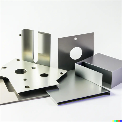
The cantilever die design is a special die technology for local punching and trimming of large sheet metal edges or parts that are inconvenient to position as a whole (such as container side panels and machine tool bed edges). Its core feature is that the die body is cantilevered and can penetrate into the interior or edge area of the part. It is suitable for materials such as low-carbon steel and high-strength steel with a thickness of 2-8mm. The punching diameter can reach 5-30mm, and the positioning accuracy is ±0.2mm. Compared with traditional dies, the cantilever structure can avoid interference between the die and other parts of the part, and is especially suitable for local processing of parts with complex contours. However, its cantilever structure is prone to deflection (need to be controlled within 0.1mm/m). Finite element analysis is required to optimize the cantilever length and cross-sectional size during design. Usually, the cantilever length does not exceed 500mm, and the cross-sectional structure adopts a box-type structure (wall thickness 15-25mm) to enhance rigidity.
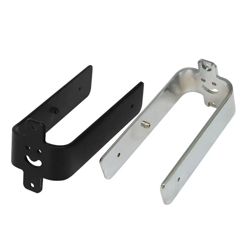
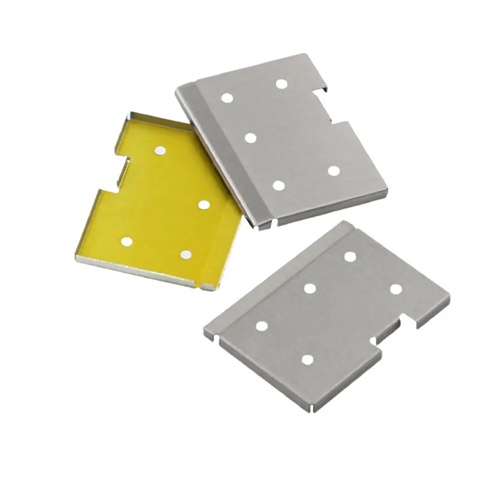
The mold structure consists of a cantilever beam, a punch assembly, a guide bracket, a feed mechanism, and a support base. The cantilever beam is forged from 45 steel (tempered hardness HB220-250) and aged to eliminate internal stresses. The punch assembly is mounted on the end of the cantilever. The punch is made of Cr12MoV steel (HRC58-62) and has a ground edge angle of 10°-15° to reduce impact. The guide bracket slides with the cantilever beam (with a clearance of 0.05-0.1mm) and moves synchronously with the punch, ensuring a perpendicularity error of less than 0.1mm/m between the punch axis and the punching surface. The guide bracket is 1/3-1/2 the extended cantilever length to suppress cantilever vibration (amplitude less than 0.05mm). The support base is secured to the workbench with expansion bolts. A leveling mechanism (with an accuracy of ±0.05mm) is installed at the connection with the cantilever beam to ensure overall levelness.
Punching force and deflection control are the key technologies. Deflection is calculated based on cantilever length and punching force. The formula is f=FL³/(3EI) (F is punching force, L is cantilever length, E is elastic modulus, and I is section inertia moment). The deflection of a 500mm long cantilever under a punching force of 100kN must be less than 0.1mm. If it exceeds the limit, the cross-sectional size must be increased or high-strength alloy materials (such as 40CrNiMoA) must be used. Punching force is calculated based on material thickness and punching area. The punching force of φ20mm of 8mm thick Q345 steel is about 120kN. It needs to be equipped with a hydraulic punching device of more than 160kN. Progressive punching (pre-pressing before punching) is used to reduce the peak load by 30%. The feeding mechanism uses a servo motor to drive the ball screw with a feeding accuracy of ±0.05mm to achieve multi-position continuous punching. The speed is controlled at 5-15 times/minute to avoid cantilever resonance.
The positioning and safety system requires a special design, using a laser locator (accuracy ±0.1mm) to project the punching position, and magnetic auxiliary positioning blocks (suction force >500N) to secure the parts. For curved parts, custom-made conformal support blocks (fit >90%) are required. Safety features include dual protection: an infrared barrier immediately shuts down the machine upon detecting a person’s approach (response time <0.1 seconds), and mechanical limits (accuracy ±0.5mm) are set at the end of the punch stroke to prevent damage from overtravel. The operating area is equipped with an emergency stop button and an audible and visual alarm system, and noise levels during punching are kept below 85dB (with a soundproof enclosure).
During commissioning and maintenance, focus on rigidity calibration. During die testing, a laser interferometer is used to measure cantilever deflection. If deflection exceeds tolerance when loaded to 120% of the rated blanking force, additional reinforcing ribs (8-12mm thick) should be added. The guide bracket should be inspected for wear every 200 cycles (replace the copper sleeve if the clearance is greater than 0.1mm). The punch cutting edge should be reground every 500 cycles (replace if the radius is greater than 0.2mm). During long-term storage, the cantilever should be adjusted to a horizontal position, the cantilever beam surface should be coated with anti-rust oil, and the guide areas should be lubricated with grease to prevent rust and seizure.