Design of automatic unloading bending die
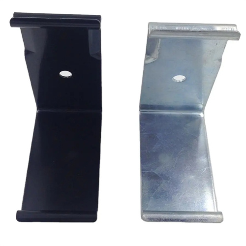
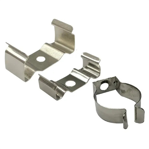
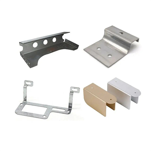
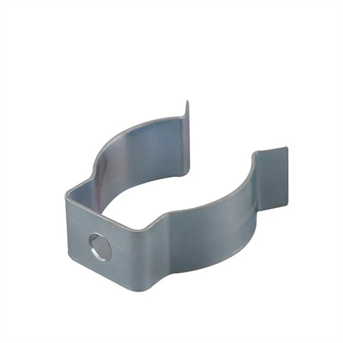
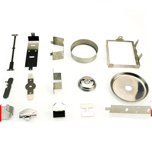
The design of automatic unloading bending die is an efficient forming equipment integrating bending and automatic unloading functions. It is suitable for small bending parts (such as electronic connectors, hardware buckles) produced in batches. It can be used for copper strips and steel strips with a thickness of 0.1-3mm. It can achieve 90°-135° bending, angle accuracy of ±0.3°, unloading time of <0.5 seconds, and production efficiency of 200-400 pieces/minute. Its core is to automatically eject or push the parts out of the mold after the bending is completed through a mechanical linkage mechanism, reducing manual intervention and labor intensity, and is particularly suitable for automated production line integration. When designing, the unloading method needs to be selected according to the shape of the part: small parts use ejector unloading, and complex shape parts use pneumatic pusher to ensure smooth unloading without jamming.
The mold structure consists of a bending mechanism (punch and die), an automatic unloading assembly (ejector/push rod, return spring), a feed guide, and a control system. The bending punch is constructed of Cr12MoV steel (HRC 58-62), with the working portion designed to the part’s bending radius (R = 0.5-5mm) and a surface coating (TiN, 0.005mm thick) for improved wear resistance. The die utilizes a carbide insert with a clearance of 8%-12% of the material thickness. A discharge channel (1-2mm larger in diameter than the part) is located at the bottom of the die. The ejector of the automatic unloading assembly is constructed of quenched and tempered 45 steel (HRC 30-35), with a polyurethane buffer (60 Shore A hardness) installed at the top to prevent damage to the part surface. The return spring uses a rectangular cross-section spring to provide a stable return force (0.5-2kN).
The coordination of unloading and bending is a key technical issue. A cam or linkage mechanism achieves timing control: the bending punch descends to contact the material → bending is completed → the punch ascends to half its stroke → the unloading assembly activates → the part is ejected → the unloading assembly resets. The entire cycle time is controlled within 0.15-0.3 seconds to ensure alignment with the feeding rhythm. For bent parts with holes, positioning hole detection is performed simultaneously with unloading. Fiber optic sensors confirm that the hole position is acceptable before unloading, and defective parts are automatically rejected (rejection response time < 0.1 seconds).
The bending process parameters must match the unloading action, and the bending speed must be controlled at 50-100mm/s. A cooling system (oil temperature <40°C) must be equipped for high-speed production to prevent the mold from overheating. For materials with large springback (such as 65Mn spring steel), the bending punch angle is set to 1°-3° for over-bending compensation, and the ejection force during unloading is 10%-15% of the bending force to avoid deformation of parts. The feeding guide uses a precision guide rail (positioning accuracy ±0.01mm) and cooperates with a servo feeder to ensure accurate material feeding position and provide a stable foundation for automatic unloading.
During debugging and maintenance, attention should be paid to the coordination of actions. During the mold trial, the action sequence of bending and unloading should be recorded by a high-speed camera. If there is a lag in unloading, the cam phase should be adjusted (±0.5°); if the part is deformed, the ejection force should be reduced (0.1kN each time). After every 10,000 pieces of work, check the wear of the unloading assembly (replace the ejector rod when the wear is greater than 0.1mm), clean the debris in the unloading channel, and add long-term grease (temperature resistant to 120°C) to the motion joint. The control system performs parameter backup every month, and the sensor is calibrated regularly (detection accuracy deviation <0.01mm) to ensure long-term stable operation. When the mold is stored, the unloading assembly needs to be reset to the initial position, and soft paper should be placed between the bending punch and the die to prevent edge damage.