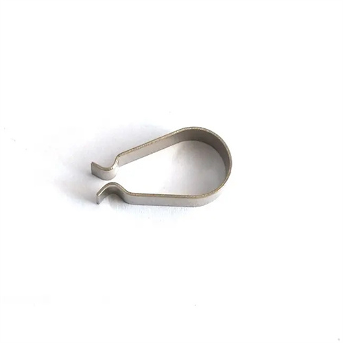
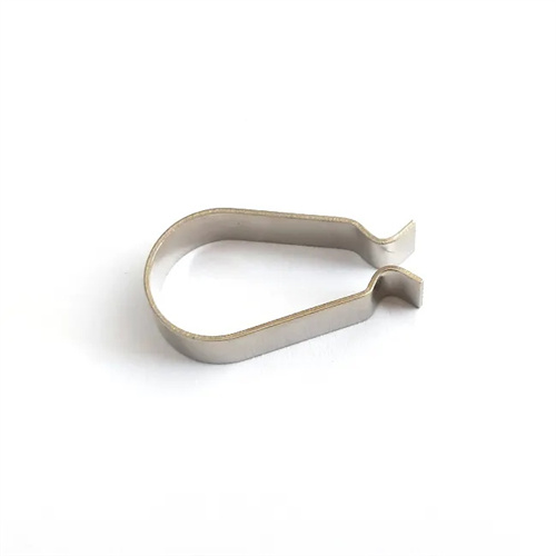
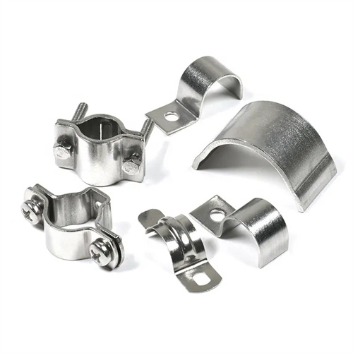
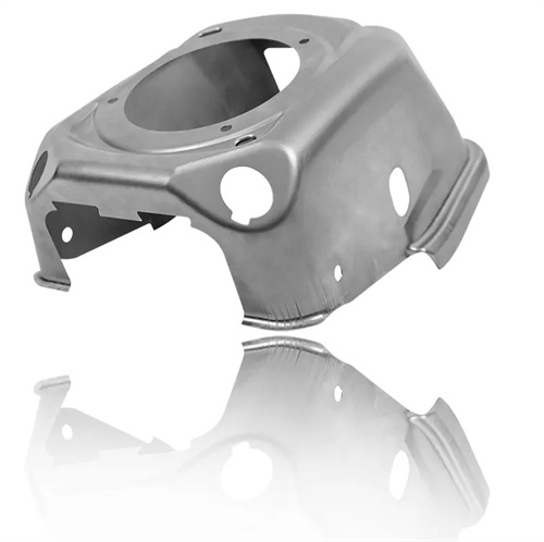
Selection of trimming allowance for drawn parts
The trimming allowance for drawn parts refers to the amount of excess material removed after drawing to ensure the accuracy of the part’s mouth size and shape. Its proper selection directly impacts part quality and material utilization. Excessive trimming allowance increases material consumption and the workload of the trimming process; too little trimming allowance can lead to substandard part dimensions after trimming due to unevenness or dimensional deviations at the drawn part’s mouth. The selection of trimming allowance should be determined based on the part’s shape, size, accuracy requirements, and the number of deep draws, while also considering relevant design standards and production experience.
The trimming allowance for cylindrical drawn parts is primarily related to the drawing height and the number of draws. The greater the height and the number of draws, the greater the unevenness at the mouth, and the larger the required trimming allowance. For cylindrical parts formed in a single draw, the trimming allowance δ can be selected according to the following empirical values: when the drawing height h ≤ 50mm, δ = 1-2mm; when 50mm < h ≤ 100mm, δ = 2-3mm; when h > 100mm, δ = 3-5mm. For cylindrical parts formed in multiple draws, since each draw increases the unevenness at the mouth, the trimming allowance needs to be increased appropriately, generally 50%-100% greater than that of a single draw. For example, for a cylindrical part with a height of 150mm formed in multiple draws, the trimming allowance δ = 5-8mm. The specific value of the trimming allowance also needs to take into account the plasticity of the material. The trimming allowance for materials with good plasticity (such as low carbon steel) can be slightly smaller, while the trimming allowance for materials with poor plasticity (such as high carbon steel) needs to be slightly larger.
The trimming allowance of flanged drawn parts includes the allowance of the flange part and the barrel mouth. The trimming allowance δ₁ of the flange part is mainly used to ensure the flatness and dimensional accuracy of the flange, and the trimming allowance δ₂ of the barrel mouth is used to ensure the height of the barrel. The selection of the flange trimming allowance δ₁ is related to the flange diameter and the number of drawing times: when the flange diameter d₁ ≤ 100mm , δ ₁ = 1~2mm ; when 100mm
The trimming allowances for rectangular drawn parts must be determined separately due to the differences between straight edges and corners. The trimming allowance δ₁ is smaller for straight edges because they deform more evenly during the drawing process, resulting in better flatness at the edge. However, the trimming allowance δ₂ is larger for corners, as these deform more drastically, leading to unevenness and dimensional deviations at the edge. For short rectangular parts (height h ≤ 50mm ), δ₁ = 1-2mm and δ₂ = 2-3mm ; for tall rectangular parts (height h > 50mm ), δ₁ = 2-3mm and δ₂ = 3-5mm . For example, for a tall rectangular part with h = 80mm , the trimming allowance δ₁ = 2.5mm for straight edges and δ₂ = 4mm for corners . Trimming rectangular drawn parts requires a dedicated trimming die to ensure uniform trimming of straight edges and corners, avoiding steps or wavy shapes.
The selection of trimming allowance also needs to consider the part’s precision requirements and production batch size. For high-precision parts (dimensional tolerance IT8 and above), the trimming allowance should be appropriately increased to ensure that the part dimensions remain within the tolerance range after trimming. For example, the trimming allowance for ordinary precision parts is 2-3mm, while for high-precision parts, it should be increased to 3-5mm. For large-scale production, since mold wear can cause fluctuations in the size of the drawn part’s mouth, the trimming allowance should be 10%-20% larger than that for small-scale production to compensate for the effects of mold wear. For example, for cylindrical parts produced in large quantities, the trimming allowance is increased from 3mm to 3.5mm. Furthermore, in automated production lines, to accommodate robotic gripping and positioning, the trimming allowance must remain stable, typically using a larger fixed value to reduce positioning errors caused by allowance fluctuations.
Methods for determining trimming allowance include empirical method, table lookup method and trial punching method. The empirical method is based on the production experience of designers and is suitable for simple-shaped drawn parts; the table lookup method refers to the trimming allowance table in relevant design manuals (such as the “Stamping Manual”) and is selected according to the size and shape of the drawn part, with high accuracy; the trial punching method measures the unevenness and dimensional deviation of the mouth through trial samples to determine a reasonable trimming allowance, which is suitable for complex shapes or high-precision drawn parts. For example, a special-shaped drawn part was found to have a maximum deviation of 4mm at the mouth through trial punching, then the trimming allowance needs to be 5mm to ensure that all unqualified parts are removed. In actual production, a variety of methods are usually used in combination. The trimming allowance is first preliminarily determined by the table lookup method,