Arrangement, overlap, material width and material utilization
Layout, overlap, stock width, and material utilization are crucial parameters in stamping process design, directly impacting part quality, production efficiency, and manufacturing costs. Layout refers to the arrangement of stamped parts on a strip or sheet of stock; overlap refers to the excess material between parts or between a part and the edge of the strip; stock width refers to the width of the strip; and material utilization is the ratio of part area to material area. Properly designing these parameters can improve material utilization and reduce production costs while ensuring part quality.
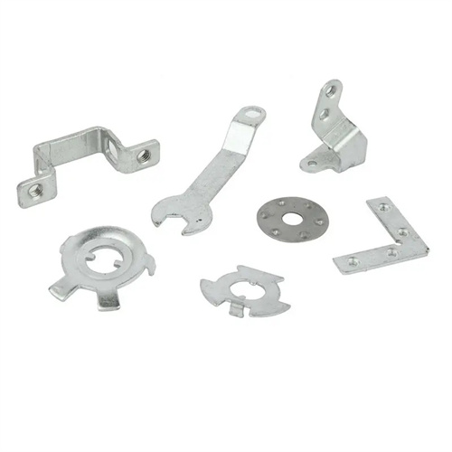
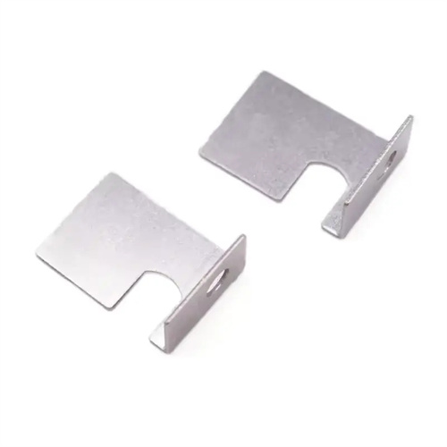
Layout design requires selecting the appropriate layout method based on the part’s shape, size, and production batch size. These methods include straight, oblique, aligned, and mixed layouts. Straight layout is suitable for simple, symmetrical parts, such as round and rectangular parts. It provides neat arrangement, facilitates feeding, and improves production efficiency, but may also result in lower material utilization. Oblique layout is suitable for parts with irregular shapes or sharp corners, such as triangles and trapezoids. Arranging them at a certain angle reduces gaps between parts and improves material utilization. Aligned layout is suitable for symmetrical parts. Parts are rotated 180° and arranged so that the protruding portion of one part aligns with the recessed portion of another, such as U-shaped and L-shaped parts. This method offers 10%-20% higher material utilization than straight layout. Mixed layout is suitable for simultaneously stamping multiple parts, allowing multiple parts to be processed in the same mold, improving production efficiency. For example, straight layout for circular gaskets ensures uniform spacing, while oblique layout for special-shaped brackets, tilted at 30°, increases material utilization from 60% to 75%.
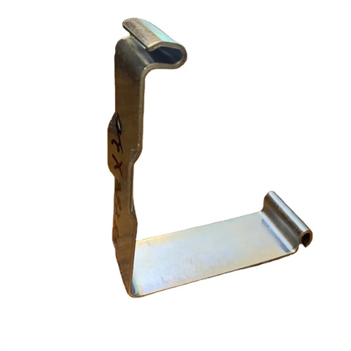
The overlap ensures sufficient rigidity for strip material feeding, prevents burrs on part edges, and compensates for positioning errors. The overlap value depends on material thickness, part shape, and layout. Thicker materials and larger parts require larger overlap values. Parts with complex shapes and sharp corners require larger overlap values to prevent tearing at corners caused by insufficient overlap. Generally, the overlap value for manual feeding is 0.5-1mm larger than that for automatic feeding. Edge overlap (the overlap between the part and the strip edge) is 1-2mm larger than the center overlap (the overlap between parts). For example, for a 1mm thick mild steel plate, the center overlap for round parts is 2mm, the edge overlap is 3mm, and the center overlap for special-shaped parts is 3mm, and the edge overlap is 4mm. Excessively small overlap values can result in insufficient strip material strength, deformation during feeding, and burrs on the part. Excessively large overlap values can reduce material utilization and increase costs.
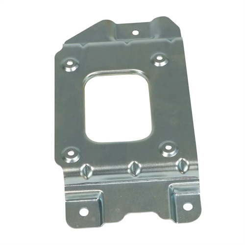
The material width must be calculated based on the maximum part width, the overlap, and the side allowance of the strip material. The formula is: Material Width B = (Maximum Part Width + 2 × Overlap) + Correction Value. The correction value accounts for strip cutting and feeding errors and is generally 0-2mm. For parts with rounded corners, the unfolded width must be calculated; for bent parts, the effect of post-bending springback on the width must be considered. The material width accuracy must be coordinated with the feeding mechanism, generally controlled within ±0.5mm to ensure smooth feeding without jamming or deflection. For example, if a stamped part has a maximum width of 50mm, a side overlap of 3mm, and a correction value of 1mm, the material width B = 50 + 2 × 3 + 1 = 57mm. Overestimating the material width results in material waste; underestimating it can lead to missing material or increased burrs on the part edges.
Material utilization is a key indicator of nesting rationality. The calculation formula is: Material utilization η = (total part area × number of nests) / (material width × pitch) × 100%, where pitch refers to the distance between two adjacent parts along the feed direction. Improving material utilization can significantly reduce production costs, especially for high-volume production and for precious materials such as stainless steel and copper alloys. This can be achieved by optimizing nesting methods, reducing overlap, and adopting waste-free nesting. For example, using parallel nesting for round parts can increase utilization by 15% compared to straight nesting, and waste-free nesting can achieve utilization rates exceeding 90%. For example, a company producing stainless steel gaskets originally used straight nesting, with a utilization rate of 65%. After switching to parallel nesting, the utilization rate increased to 82%, saving over 100,000 yuan in material costs annually.
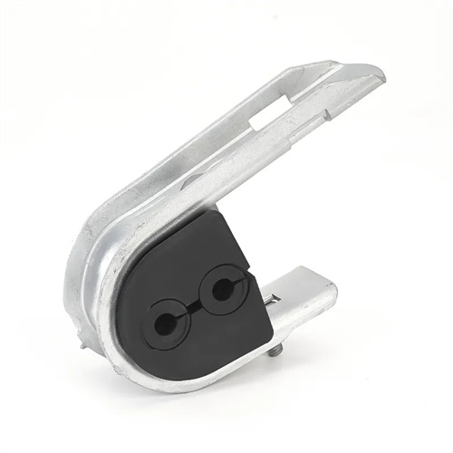
Targeted planning, overlap, and material width design for specialized parts require specific measures. For slender parts (aspect ratio > 5), a transverse overlap should be added during layout to prevent bending during feeding. For parts with holes, the distance between the hole and the overlap should be ≥ 1.5 times the material thickness to prevent tearing at the hole edge. For stepped parts, nested layout can be used, with smaller parts nested between larger ones, to improve material utilization. After the layout design is completed, it must be verified through a test punch to check material utilization, feeding smoothness, and part quality. Parameters should be adjusted based on the test results. For example, if a test punch reveals burrs on the part edge, the overlap should be increased; if feeding is not smooth, the material width or step distance should be adjusted. Through scientific design and optimization, material utilization can be maximized while ensuring part quality, achieving both economic and social benefits.