Bending part rebound method
Springback in bent parts refers to the phenomenon in which the angle and radius of a bent part change due to elastic recovery after the external bending force is removed. This is an unavoidable defect in the bending process and directly affects the dimensional accuracy of the bent part. The essence of springback is that the plastic deformation of the material during the bending process is accompanied by elastic deformation. When the external force disappears, the elastic deformation partially recovers, causing the actual angle of the bent part to be greater than the angle of the mold (angle springback) and the actual radius to be greater than the radius of the mold (radius springback). There are three main types of springback in bent parts: angle springback, radius springback, shape springback, and warpage springback. Different springback modes require different control measures.
Angular springback is the most common springback mechanism. It refers to the difference between the actual angle of the bent part and the die angle, typically expressed as Δα (Δα = actual angle – die angle). The magnitude of angular springback is related to the material’s mechanical properties, relative bend radius, bending method, and die structure. The higher the material’s yield strength and the smaller its elastic modulus, the greater the springback; the larger the relative bend radius (r/t), the greater the springback; and the larger the bend angle, the greater the springback. For example, high-strength steel (tensile strength > 600 MPa) can experience angular springback of 5°-10°, while mild steel typically experiences angular springback of 1°-3°. Angular springback can cause the bent part’s angle to be out of tolerance, necessitating angle compensation during die design. This involves reducing the die’s bend angle to compensate for the springback. For example, for a workpiece requiring a 90° bend, the die angle should be designed to 85°-88° to achieve a 90° angle after springback.
Radius springback occurs when the actual inside radius of a bent part exceeds the punch radius of the die. It’s typically expressed as Δr (Δr = actual radius – die radius). Radius springback primarily occurs when the relative bend radius is large (r/t > 5). The elastic recovery of the material increases the inside radius of the bend, and the outside radius also increases accordingly. For example, using a 10mm-radius punch to bend a 1mm-thick brass sheet, the actual inside radius after bending may reach 10.5-11mm, resulting in 0.5-1mm of radius springback. Radius springback can affect the dimensional accuracy of the bent part. Particularly for parts with critical fits, radius springback can be minimized by controlling the relative bend radius, increasing the number of bends, or employing corrective bends. For example, replacing a single bend with two bends—first bending to a smaller radius and then correcting to the desired radius—can reduce radius springback by over 50%.
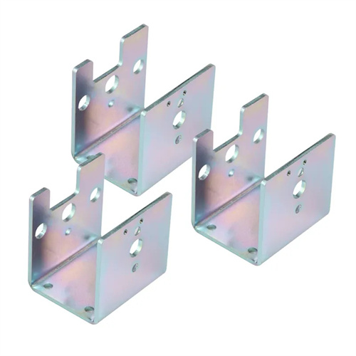
Shape springback refers to the deformation of the overall shape of complex bent parts (such as U-shaped, Z-shaped, and polygonal parts) after bending. This is typically caused by inconsistent springback in various parts. For example, a U-shaped part may exhibit outward-flashing sidewalls and inward-concave bottoms after bending. This is because the springback of the sidewalls during bending causes them to flare outward, while the bottom deforms inwards due to the tension exerted by the sidewalls. The extent of shape springback is related to the part geometry, material distribution, and mold constraints. The more complex the shape, the more difficult it is to control springback. Controlling shape springback requires a sound mold structure. For example, a U-shaped bending mold can utilize tapered sidewalls and bottom ejection devices to apply a corrective force to the sidewalls and bottom during bending, reducing springback. Alternatively, a pre-bending process can be used to pre-bend the blank into a shape opposite to the springback direction before bending, thereby offsetting some of the springback.
Warpage springback refers to the bending or twisting deformation of a bent part along its length. It primarily occurs during the bending process of long, rectangular parts (length-to-width ratio > 5) and is caused by uneven stress distribution along the length of the material. For example, after bending a long, U-shaped part, the ends may warp upward or downward, forming a saddle shape. This is because the springback at the ends is greater than in the middle, resulting in overall warpage. Warpage springback affects the assembly accuracy of the bent part and can be controlled by optimizing the blank size, increasing the pressing force, or implementing a shaping process. For example, a shaping process can be added after bending to apply pressure to the warped area to relieve stress and reduce warpage. Alternatively, a process allowance can be added to the ends of the blank and removed after bending to ensure the straightness of the main part.
Springback control methods vary depending on the springback pattern and the characteristics of the part being bent. These methods primarily include die compensation, pressurization correction, material treatment, and process adjustment. Die compensation, based on the estimated springback amount, pre-defines an opposite angle or shape during die design to offset springback. This method is suitable for both angular and shape springback. Pressurization correction applies a high corrective force to the part at the end of the bend, increasing the plastic deformation ratio and reducing elastic recovery. This method is suitable for both radius and shape springback. Material treatment reduces springback by annealing the material to lower its yield strength. This method is suitable for high-strength materials. Process adjustment controls springback by changing the bending method (such as stretch bending instead of conventional bending), increasing the number of bends, or optimizing the blank shape. This method is suitable for complex bent parts. For example, automobile door frames are bent using a stretch bending process. By applying axial tension during bending, the material undergoes more complete plastic deformation, keeping springback to within 1°.
Predicting and controlling springback in bent parts is a challenging aspect of the bending process, requiring a combination of theoretical calculations, empirical data, and CAE simulation analysis. With the advancement of computer technology, the use of finite element analysis software (such as ABAQUS and ANSYS) can accurately predict springback under different material and process parameters, providing a basis for mold design and reducing mold trials. For example, using Dynaform software to simulate the bending process of a U-shaped part, a springback angle of 3° was predicted. A bending angle of 87° was used in the mold design, and after mold trials, the bent part achieved an angle of 90°±0.5°, meeting the required accuracy. A deeper understanding of the springback mechanism and control methods for bent parts can effectively improve the dimensional accuracy of bent parts, reduce production costs, and increase production efficiency.