Calculation of the length of the bending blank
Calculating the blank length of a bent part is a crucial step in bending process design. Its purpose is to determine the length of the flat blank before bending, ensuring that the final dimensions of the part meet design requirements. Because the material undergoes plastic deformation during the bending process, the length of the neutral layer remains essentially unchanged. Therefore, blank length is typically calculated based on this layer. Accurately calculating blank length avoids material waste and ensures dimensional accuracy of the bent part. This can significantly reduce production costs, especially for mass-produced parts.
For simple V-bends, the blank length calculation requires considering both the straight segment length and the curved arc segment length. The straight segment length is the sum of the actual lengths of the part’s straight sides, while the curved arc segment length is calculated based on the neutral layer radius using the formula: L = l1 + l2 + (π × α × rmid)/180, where l1 and l2 are the straight segment lengths on either side, α is the bend angle (degrees), and rmid is the neutral layer radius. The neutral layer radius rmid = r + kt (r is the inner bend radius, t is the material thickness, and k is the neutral layer displacement coefficient). The k value varies with the relative bend radius (r/t). The smaller the r/t, the smaller the k value. For example, when r/t = 0.5, k = 0.3; when r/t = 5, k = 0.5. For example, the straight side lengths of the V-shaped part are 30mm and 40mm respectively, the bending angle is 90°, the inner radius is 5mm, and the material thickness is 2mm (r/t=2.5, k=0.45), then r mid = 5 + 0.45×2=5.9mm, the arc segment length = (π×90×5.9)/180≈9.27mm, and the total length of the blank = 30+40+9.27=79.27mm.
The blank length calculation for U-shaped parts is similar to that for V-shaped parts, but requires consideration of two curved arcs and three straight segments (the two straight sides and the bottom). The formula is: L = l1 + l2 + l3 + 2 × (π × α × r) / 180, where l1 and l2 are the lengths of the two straight sides, l3 is the length of the straight segment at the bottom, and α is the bend angle of one side (usually 90°). Note that the straight segment length at the bottom of the U-shaped part refers to the actual length of the bottom after bending, not the original blank length. Deformation during bending must be accounted for in the calculation. For example, the straight sides of the U-shaped part are 25 mm long, the bottom length is 30 mm, the bending angle is 90°, the inner radius is 3 mm, the material thickness is 1 mm (r/t=3, k=0.48), r middle = 3 + 0.48×1=3.48 mm, the length of a single arc segment = (π×90×3.48)/180≈5.46 mm, and the total length of the blank = 25+25+30+2×5.46=80+10.92=90.92 mm.
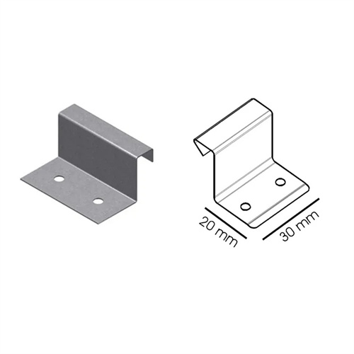
To calculate the blank length of complex bent parts (such as polygons and Z-shaped parts), the part must be broken down into multiple simple straight and arc segments, which are then calculated separately and summed. The decomposition requires specifying the angle, radius, and straight-side length of each bend to ensure smooth connections between segments. For Z-shaped parts, which typically consist of two bend angles and three straight segments, the calculation requires determining the neutral radius of each curved arc and then summing the lengths of each segment. For example, a Z-shaped part has three straight sides of 15mm, 20mm, and 15mm, with both bend angles at 90°, an inner radius of 2mm, and a material thickness of 1mm (r/t = 2, k = 0.43). r mid = 2 + 0.43 × 1 = 2.43mm. The length of a single arc segment is approximately (π × 90 × 2.43)/180, which is 3.81mm. The total blank length is 15 + 20 + 15 + 2 × 3.81 = 50 + 7.62 = 57.62mm.
The calculation of blank length must take into account the effects of material elongation and springback on dimensions. For materials with good ductility (such as brass and aluminum alloys), slight elongation may occur after bending, and a correction of 0.1%-0.3% must be subtracted from the calculation. For brittle materials such as high-strength steel, the length change after bending is minimal and can be ignored. Furthermore, trial bending verification is a key step in ensuring the accuracy of blank length. The actual dimensions of the test specimens are measured and compared with the designed dimensions to correct the blank length. For example, a low-carbon steel U-shaped part was calculated to have a blank length of 90.92mm. After trial bending, the total length was found to be 1.2mm longer than the designed length. After adjusting the blank length to 89.72mm, the bent part met the required dimensions.
When calculating the blank length for special bending processes (such as stretch bending and roll bending), the specific characteristics of the process must be taken into account. Stretch-bent parts experience a slight elongation due to axial tension, requiring an additional 0.5%-1% compensation in the calculation. For roll-bent parts, the blank length must be precisely calculated based on the bend radius and arc length to avoid uneven ends. With the advent of computer technology, CAD software (such as AutoCAD and SolidWorks) can be used to directly measure the neutral layer length of bent parts, improving calculation efficiency and accuracy. For example, after creating a 3D model of a bent part in SolidWorks, the “Measure” tool can be used to directly obtain the total neutral layer length, which serves as the basis for blank length design and reduces manual calculation errors.